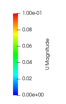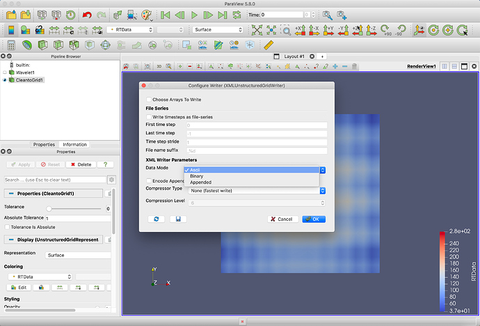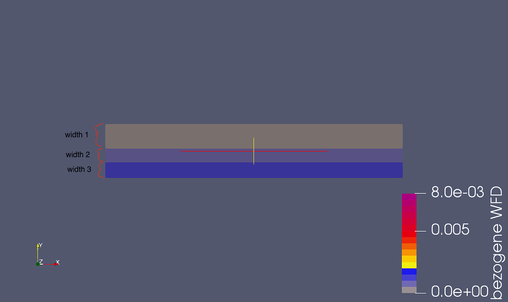

You can of course convert any image formats to anything else using Slicer using the GUI (load the data set into Slicer then choose a different format when you save the data) or running this Python command: (loadVolume('/path/to/input.vtk'), '/path/to/output.nrrd')īut it makes your life simpler if you use the same file format across all software in your workflow. Paraview doesn’t document its legend format very well, however, there is a good resource that defines the types of legend tick here: When you edit a colour map there is an option to edit the legend: And here you can change to advance settings and alter the tick formats: Here the format will produce a float with a single decimal place for both the ticks and the ranges, further by using custom. nrrd, so if you use ParaView a lot then you may prefer to use.

Finally, we already have 3 other widely used file formats (nrrd, nifti, and mha), so you really don’t want to complicate things with bringing in yet another one. If Automatic Label Format is checked, ParaView will try to pick an optimal representation for numerical values based on the value and available screen space. Also, the format can only store 4D images (so you, cannot store a 3D+t color volume) and there is no way to specify what the 4th dimension contains (color, displacement, etc.). The limitation that instantly disqualifies this file format from serious use for medical imaging that it cannot store image axis directions (it always assumes image IJK axes are the same as patient LPS axes). Although our chosen domain is in 2D, the function in ParaView that converts our table to a structured grid requires three coordinates.I would not recommend using. Effectively, z = 0 is defined for all points. As already mentioned, note that the x-values are the ones changing the fastest. The file formats that ParaView understands includes at least the ones described in the in tool help (Help->ParaView->Readers).
#Paraview label format how to
This is to not get any errors when importing into ParaView. This page describes different data formats that ParaView can read and gives guidance over how to use them. The top row in the example "x3 圓 z1" is in ParaView only used to describe the column, thus the values below. By unchecking it, you can explicitly specify the printf -style format to use for numeric values. So, when we later get into ParaView, we will not have to remember which column represented what, but rather just look at the descriptor. If Automatic Label Format is checked, ParaView will try to pick an optimal representation for numerical values based on the value and available screen space. The numbers behind the x, y and z is something I picked up from Prof. Bailey's great tutorial on ParaView (see ParaView). They simply describe how many points there are in the current direction, thus for our box geometry of 3 x 3 x 1 nodes we get as shown above. This is helpful knowledge when we later are to convert the points to a structured grid. Lastly, if we have some results we wish to add, simply insert them as an additional column. To import a file into ParaView, click Open or CTRL + O and located your file.

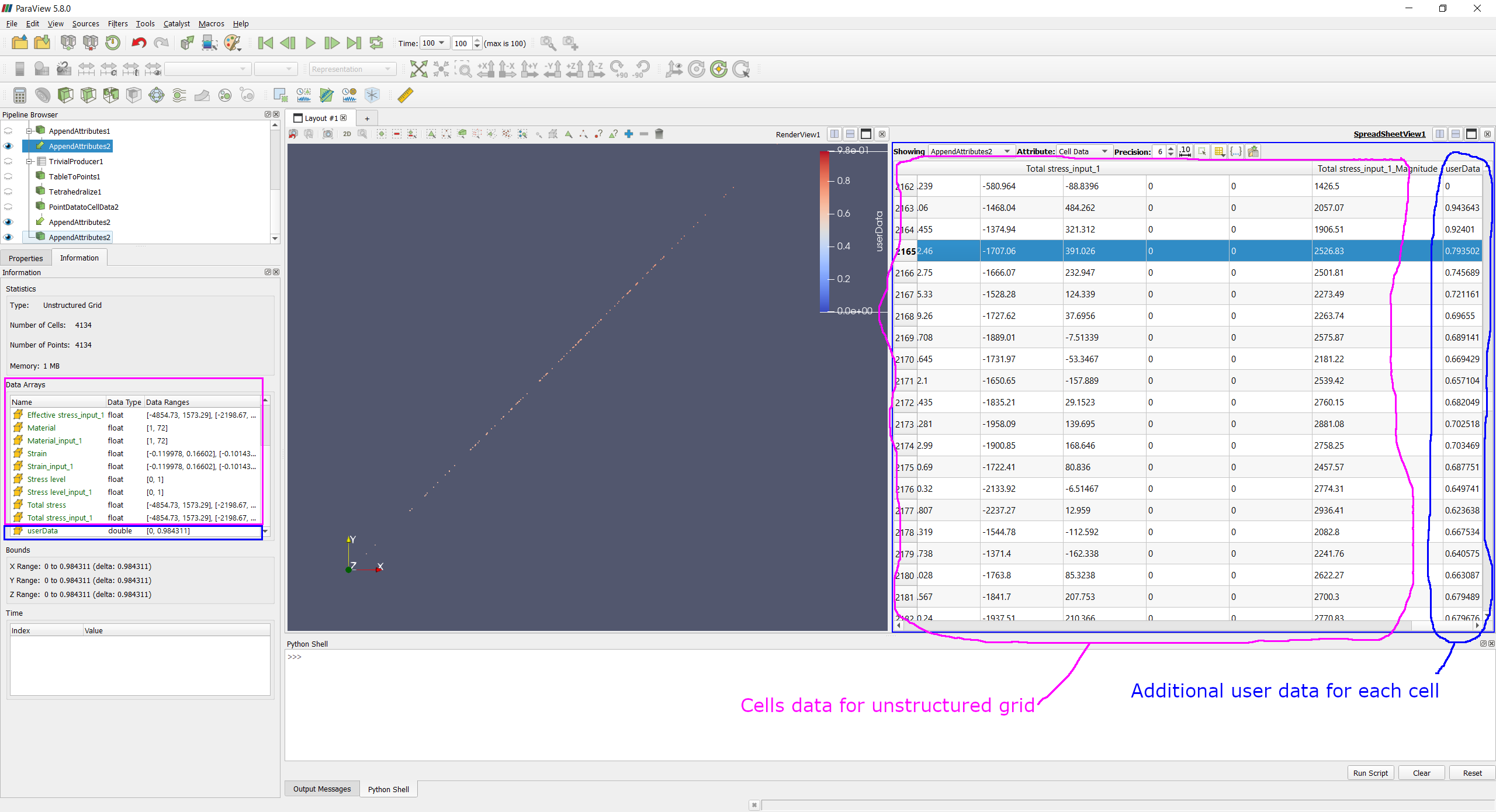
To make it a bit more interesting, we will use example_2.csv which is attached in the section above. Then, click Apply, and a table should pop up. that the x-values are actually listed in the column named x256, z-coordinates in the column named z1 etc. Based on which data attribute the view is currently showing, i.e. If your file is not separated by commas, but by e.g. To create a selection in the SpreadSheet View, you simply click on the corresponding rows in the spreadsheet.You can use the CTRL (or ) and keys to add to the selection. semi-colons, simply change the Field Delimiter Character under Properites (lower left in image below). The easiest way to visualize your data is through single points. To do so, go to Filters → Alphabetical → Table To Points. Then, select the correct columns for x, y and z and click Apply. If nothing shows up in the graphics window, click on it and then click on the eye next to points created under Pipeline Browser. Also, make sure the coloring of the points is set to differ from the background color. Making a structured grid is not very different from single points, but because of ParaView's automatical interpolation, it is most often desired. It also makes it a bit easier to interpret, as we get a complete, continuous geometry.

To make a structured grid, go to Filters → Alphabetical → Table To Structured Grid. Then, select the correct columns for x, y and z and fill in the correct values for Whole Extent. Whole extent may be thought of as the domain size for each direction.


 0 kommentar(er)
